
On this page
- Quick answer: how much rebar do I need?
- What to measure before calculating
- How to calculate rebar for a rectangular slab
- Rebar spacing versus quantity
- Worked rebar quantity examples
- Rebar quantity table for common slab sizes
- How many pieces of rebar do I need for a slab?
- Common US rebar sizes and metric bars
- Lap splices, bends and waste
- Layouts that need more than a simple grid estimate
- Common rebar estimating mistakes
- Keep concrete volume and rebar quantity separate
- Technical references and design boundaries
Quick answer: how much rebar do I need?
Rebar quantity depends mainly on the slab or footing dimensions, bar spacing, bar directions, number of reinforcement layers, required lap/splice lengths, edge clearances and project-specific structural requirements.
For a rectangular, two-way grid, count the bars in each direction, multiply each count by its required bar length, and add the results. Then account for specified laps, hooks, bends, extra reinforcement and cutting losses.
The Calcavera Rebar Calculator helps estimate material quantity. It does not design reinforcement. Final bar sizes, spacing, cover, splices and layout must follow approved plans, applicable codes and engineering requirements.
What to measure before calculating
- Length and width: identify the dimensions of each slab panel, footing or other reinforced section.
- Specified spacing: check whether spacing differs between directions or zones.
- Bar size: use the size shown on the plans, not a size selected by the calculator.
- Reinforcement layers: distinguish one grid from separate upper and lower mats.
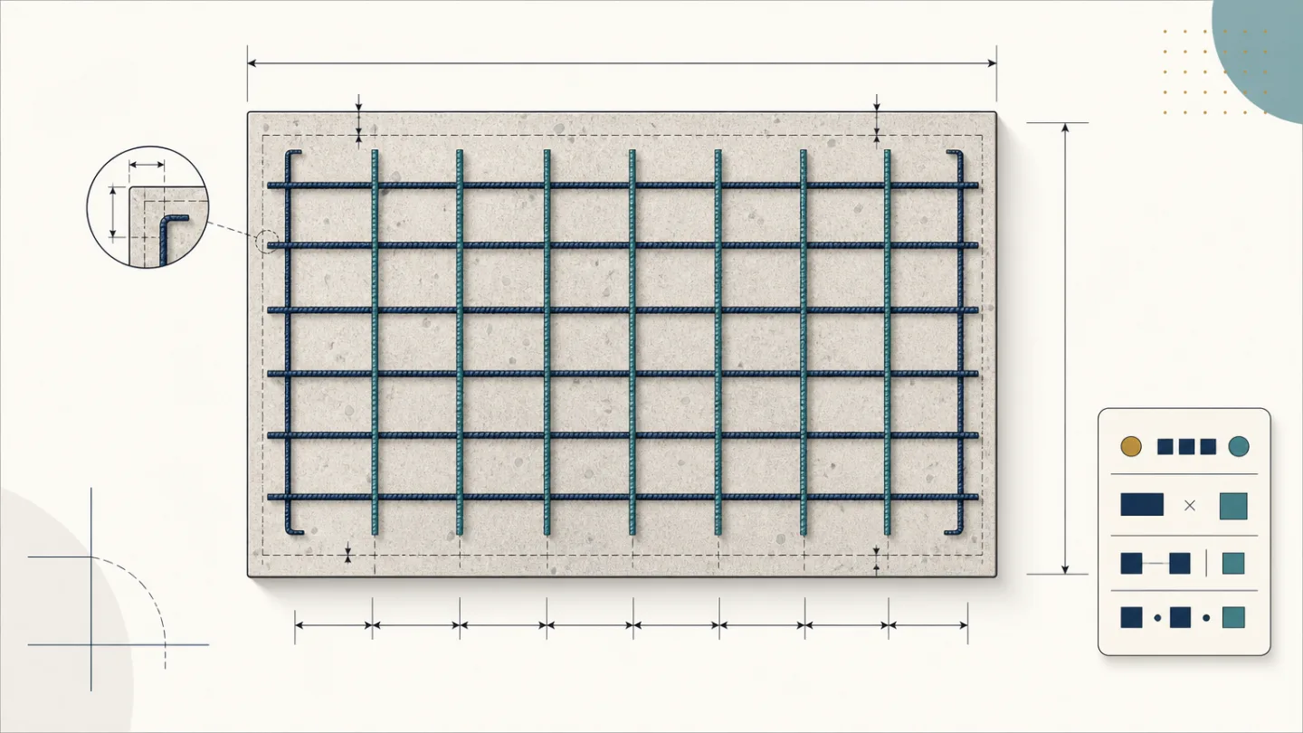
- Concrete cover and edge details: determine the bar-end setbacks and outer bar centerline positions.
- Additional details: include laps, hooks, bends, openings, beams, thickened edges and construction joints.
- Available stock lengths: confirm what your supplier can deliver before making a cutting schedule.
Concrete cover is measured to the reinforcement surface, not its centerline. For an outer straight bar, its centerline setback generally includes the specified side cover plus half its diameter. Bar-end clearance and the centerline setback used to count parallel bars are therefore not always identical.
How to calculate rebar for a rectangular slab
1. Determine the usable spans and cut lengths
Label the slab length L and width W. Bars running along L are distributed across W; bars running along W are distributed across L. This distinction prevents counting bars against the wrong dimension.
Use the distance between the first and last bar centerlines as the covered dimension for counting. Separately determine each bar's cut length from its end clearances and any required detailing.
2. Choose the specified spacing
Use the spacing required by the design. Keep units consistent: 12 inches equals 1 foot, 18 inches equals 1.5 feet, and 200 millimetres equals 0.2 metres.
3. Count bars in both directions
Approximate number of bars = covered dimension ÷ spacing + 1.
When bars are required at both limits of a usable span and the specified spacing is a maximum, use:
Number of bars = round up(covered dimension ÷ maximum spacing) + 1.
The +1 counts the additional end bar. Rounding up the number of spaces prevents an evenly distributed layout from exceeding the selected maximum spacing. Drawings may instead specify a fixed spacing with a shorter final bay or another edge arrangement.
4. Calculate total length
Total rebar length = (bars in direction A × bar length A) + (bars in direction B × bar length B).
If directions have different bar sizes, keep their quantities separate. Apply the same principle to different reinforcement layers and reinforcement zones.
5. Add detailing and convert to purchased bars
- Add the lengths required for specified laps, hooks and bends.
- Add separate bars at openings, joints, beams and thickened edges.
- Prepare a cutting schedule using available stock lengths.
- Identify reusable offcuts and unavoidable cutting losses.
- Add a justified project-specific allowance where appropriate.
Rebar spacing versus quantity
Common calculation examples use 6, 8, 12, 16, 18 or 24 inches on center. These are comparison values, not recommendations for a particular slab.
- Closer spacing increases bar count: more bars fit across the same usable span.
- Larger slabs increase count and length: bars become longer, and more bars are needed across the wider dimensions.
- A second identical layer approximately doubles grid material: differences in cover, detailing and local reinforcement can change the final total.
- Irregular geometry needs separate calculations: estimate each section and reconcile shared bars, overlaps and intersections.
For a large, uniform two-way grid with equal spacing s, an approximate length density is 2 ÷ s. If s is measured in feet, the result is linear feet of rebar per square foot. At 12-inch spacing, that is approximately 2 linear feet per square foot before edge effects, laps and extra bars. Small slabs can differ noticeably because boundary bars make up a larger share of the total.
Worked rebar quantity examples
The slab examples below use one layer, equal spacing in both directions and straight bars, unless stated otherwise. To keep the arithmetic readable, they assume a 2-inch setback both for bar ends and for outer bar centerlines. That is a calculation assumption—not a specified concrete-cover requirement. Use the actual cover, bar diameter and edge details from your plans.
Example 1: rebar for a 10 × 10 ft slab at 12-inch spacing
- Usable span and straight cut length: 10 ft − 4 in = 9 ft 8 in, or 9.6667 ft.
- Bars running along the length: round up(9.6667 ÷ 1) + 1 = 11.
- Bars running along the width: 11.
- Total individual grid bars: 11 + 11 = 22.
- Total length: 22 × 9.6667 = approximately 212.7 linear feet.
If evenly distributed between the outer bar centerlines, the ten spaces are approximately 11.6 inches each. This is below the selected 12-inch maximum.
Ignoring edge setbacks gives the familiar rough estimate of 22 bars × 10 ft = 220 linear feet. Use that only as an initial comparison, not a cutting list.
Example 2: rebar for a 20 × 20 ft slab at 12-inch spacing
- Usable span and straight cut length: 20 ft − 4 in = 19 ft 8 in, or 19.6667 ft.
- Bars per direction: round up(19.6667 ÷ 1) + 1 = 21.
- Total individual grid bars: 42.
- Total length: 42 × 19.6667 = 826 linear feet.
The full-dimension planning estimate is 42 × 20 = 840 linear feet. Neither total includes laps, hooks or additional local reinforcement.
Example 3: a 12 × 30 ft driveway slab at 18-inch spacing
This demonstrates quantity calculation only; it does not establish suitable driveway reinforcement.
- Usable width: 12 ft − 4 in = 11.6667 ft.
- Usable length: 30 ft − 4 in = 29.6667 ft.
- Long bars: round up(11.6667 ÷ 1.5) + 1 = 9 bars.
- Short bars: round up(29.6667 ÷ 1.5) + 1 = 21 bars.
- Total length: (9 × 29.6667) + (21 × 11.6667) = 512 linear feet.
If the supplier's stock bars are shorter than the required long bars, the design must address the splices. Do not simply join short bars wherever convenient.
Example 4: a rectangular concrete footing
Assume a hypothetical 20 ft long, 2 ft wide footing whose design calls for three straight longitudinal bars and straight transverse bars at a maximum 12-inch spacing. For this example only, use a 3-inch setback for bar ends and the outer transverse bar centerlines.
- Longitudinal cut length: 20 ft − 6 in = 19.5 ft.
- Longitudinal total: 3 × 19.5 = 58.5 ft.
- Transverse cut length: 2 ft − 6 in = 1.5 ft.
- Transverse count: round up(19.5 ÷ 1) + 1 = 21.
- Transverse total: 21 × 1.5 = 31.5 ft.
- Combined straight-bar total: 90 linear feet.
This is not a complete footing design. Actual footing reinforcement may include bent transverse bars, ties, dowels, hooks, starters or other reinforcement. Concrete placed against soil can also have different cover requirements. Use the specified details.
Example 5: two reinforcement layers
If the 20 × 20 ft slab example has two identical grids:
826 ft per layer × 2 layers = 1,652 linear feet.
That is 84 individual straight grid bars. Count chairs, support bars, ties and any additional reinforcement separately. Upper and lower mats may use different bar sizes, spacing or lengths, so calculate them independently when they differ.
Use the Calcavera Rebar Calculator to compare quantities for your specified dimensions and spacing, then reconcile the result with the drawings and a cutting schedule.
Rebar quantity table for common slab sizes
The table uses a simplified one-layer, two-way grid. Counts are round up(full slab dimension ÷ spacing) + 1, and bars are treated as the full slab length or width. Values are total linear feet, with no cover deductions, laps, bends or waste. These are planning comparisons, not fabrication quantities or reinforcement recommendations.
| Slab size | 6 in spacing | 8 in spacing | 12 in spacing | 16 in spacing | 18 in spacing | 24 in spacing |
|---|---|---|---|---|---|---|
| 10 × 10 ft | 420 ft | 320 ft | 220 ft | 180 ft | 160 ft | 120 ft |
| 12 × 12 ft | 600 ft | 456 ft | 312 ft | 240 ft | 216 ft | 168 ft |
| 20 × 20 ft | 1,640 ft | 1,240 ft | 840 ft | 640 ft | 600 ft | 440 ft |
| 12 × 30 ft | 1,482 ft | 1,122 ft | 762 ft | 588 ft | 522 ft | 402 ft |
How many pieces of rebar do I need for a slab?
There are two different counts:
- Installed bars: individual lengths required by the layout, including separate splice pieces where applicable.
- Purchased stock bars: supplier-length bars from which those pieces are cut.
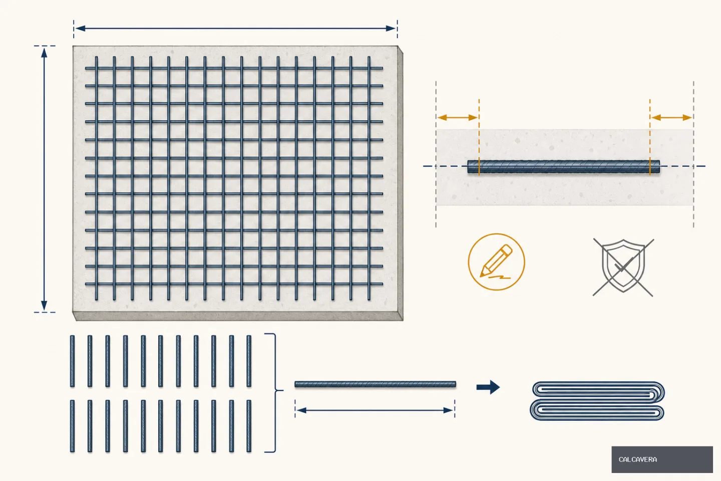
Theoretical minimum stock-bar count = round up(total required length ÷ stock-bar length).
This gives only a lower bound. For example, twelve 12-foot cuts require 144 feet of material. Dividing by 20-foot stock gives round up(144 ÷ 20) = eight bars. But each 20-foot bar yields only one unspliced 12-foot piece, so the cutting schedule requires twelve stock bars, unless suitable offcuts or another approved arrangement are available.
In the 10 × 10 ft worked example, two 9 ft 8 in pieces fit into one 20-foot stock bar. Eleven stock bars can therefore provide the 22 straight pieces, before any additional detailing or allowance.
You may encounter 20-foot or 40-foot stock in US supply and 6-metre or 12-metre stock in metric markets. Confirm local availability; stock lengths vary by supplier, product and market.
Common US rebar sizes and metric bars
Bar size affects diameter, weight, detailing and structural performance. It does not automatically change a grid's straight-line length when spacing and layout stay the same.
The following nominal dimensions and weights are consistent with the reinforcing-bar data in ASTM A615/A615M and CRSI technical references. Nominal diameter is an equivalent round-bar dimension, not a measurement across the deformations.
| US bar size | Nominal diameter | Nominal weight |
|---|---|---|
| #3 | 3/8 in | 0.376 lb/ft |
| #4 | 1/2 in | 0.668 lb/ft |
| #5 | 5/8 in | 1.043 lb/ft |
| #6 | 3/4 in | 1.502 lb/ft |
Estimated nominal weight = total length for a bar size × its nominal weight per unit length. For example, 826 ft of #4 bar corresponds to approximately 552 lb before adding other reinforcement.
Metric projects may specify bars by nominal diameter, such as 10 mm, 12 mm, 16 mm or 20 mm. Do not treat these as exact substitutes for US bar numbers. Product standards, steel grade, nominal area and detailing requirements must also match the design.
Metric quantity example
For a hypothetical 3 m × 4 m grid with 200 mm maximum spacing, assume 50 mm setbacks for both bar ends and outer bar centerlines:
- Usable spans: 2.9 m and 3.9 m.
- Bars running along the 4 m direction: round up(2.9 ÷ 0.2) + 1 = 16.
- Bars running along the 3 m direction: round up(3.9 ÷ 0.2) + 1 = 21.
- Total straight length: (16 × 3.9) + (21 × 2.9) = 123.3 m.
The selected bar diameter remains a separate design input. The setbacks and spacing above are arithmetic assumptions, not universal metric construction requirements.
Lap splices, bends and waste
A lap splice overlaps bars to transfer force. Required lap length depends on bar size, concrete properties, reinforcement conditions, applicable code and engineering design. There is no universal lap length. Use the approved splice schedule, including permitted locations and any staggering requirements.
Where a specified run is assembled from overlapping pieces, its combined cut length includes the overlap. For example, one specified lap of length l adds l to the combined material length needed for that run, before other detailing.
Hooks and bends also need their specified developed lengths. Use the bar schedule or approved detailing method rather than measuring only the straight distance between endpoints.
Separate required material from waste:
- Required material: grid bars, specified laps, hooks, bends and additional reinforcement.
- Cutting loss: lengths left over after producing the required pieces.
- Reusable offcuts: pieces that can satisfy other scheduled cuts without unauthorized splicing.
- Project allowance: an allowance justified by the job's handling, complexity and uncertainty.
Do not apply one waste percentage to every project. A repetitive grid with efficient cuts can have very different losses from a footing cage with many bent shapes.
Layouts that need more than a simple grid estimate
- Openings: deduct omitted bars only after checking required trimming and replacement reinforcement.
- Beams and thickened edges: count their longitudinal bars and ties separately.
- Construction joints: include specified dowels, continuity bars and splice details.
- Multiple mats: separate upper and lower quantities by bar size and spacing.
- L-shaped or irregular slabs: estimate section by section and avoid double-counting shared reinforcement.
- Hooks and bent bars: calculate scheduled cut lengths, not just projected dimensions.
Common rebar estimating mistakes
- Counting only one direction: a two-way grid needs both sets of bars.
- Forgetting the +1 end bar: ten spaces require eleven bars when both ends are occupied.
- Mixing inches and feet: convert spacing before dividing dimensions.
- Ignoring edge cover: distinguish bar-end clearance from outer bar centerline setback.
- Forgetting lap splices: overlaps increase the combined cut length.
- Missing a second reinforcement layer: check the entire reinforcement schedule.
- Confusing linear feet with stock pieces: verify that the required cuts fit the available stock.
- Treating a calculator as a design tool: material arithmetic does not establish structural adequacy.
Keep concrete volume and rebar quantity separate
This guide estimates reinforcement, not concrete volume. For the separate concrete takeoff, consult Calcavera's How Much Concrete Do I Need? Complete Slab, Footing & Bag Guide, How to Calculate Concrete for a Slab: Cubic Yards & Volume Guide, Concrete Slab Calculator or Concrete Footing Calculator.
Technical references and design boundaries
- Concrete Reinforcing Steel Institute (CRSI): reinforcing-bar dimensional data and the Manual of Standard Practice for reinforcement detailing and fabrication practices.
- ASTM A615/A615M: Standard Specification for Deformed and Plain Carbon-Steel Bars for Concrete Reinforcement, including nominal bar dimensions and weights.
- American Concrete Institute (ACI): ACI 318, Building Code Requirements for Structural Concrete, for applicable structural-concrete design and detailing provisions.
Use the current technical publications and the code edition applicable to your project. These references do not make any example spacing, cover assumption or footing arrangement in this guide a universal requirement. Approved project drawings and engineering instructions govern the final reinforcement.
Frequently asked questions
How much rebar do I need for a 10x10 slab?
For an illustrative one-layer grid at 12-inch maximum spacing, with an assumed 2-inch clearance from each slab edge to the bar ends and outer bar centerlines, allow 11 bars in each direction. Each straight bar is 9 ft 8 in long, giving approximately 212.7 linear feet before laps, bends and cutting losses. A simplified full-dimension estimate gives 220 linear feet. Neither example establishes the correct reinforcement design for your slab.
How far apart should rebar be?
Use the spacing specified by the approved structural plans and applicable requirements. Values such as 6, 8, 12, 16, 18 and 24 inches are useful for comparing material quantities, but none is a universal recommendation.
How many pieces of rebar are needed for a concrete slab?
First calculate the individual grid bars in both directions. Then prepare a cutting schedule using your supplier's stock lengths. Dividing total required length by stock length and rounding up gives a theoretical minimum, not necessarily the actual number of stock bars to buy.
How do I calculate rebar spacing?
If N bars are evenly distributed across a usable centerline span D, the spacing is D ÷ (N − 1). To estimate the number of bars needed for a specified maximum spacing s, use N = round up(D ÷ s) + 1. Keep all dimensions in the same units.
Does a thicker slab need more rebar?
Not automatically. Reinforcement depends on loads, support conditions, structural behavior, exposure and the approved design—not slab thickness alone. A different design may require larger bars, closer spacing, extra local bars or another reinforcement layer.
How much extra rebar should I order?
Calculate required laps, hooks, bends and extra bars first, then use a cutting schedule to identify offcuts and unusable lengths. Add a project-specific allowance for handling and changes where appropriate. There is no universal waste percentage or lap allowance.
How long are standard rebar bars?
Stock lengths vary by supplier and market. You may encounter 20-foot or 40-foot bars in US supply and 6-metre or 12-metre bars in metric markets, but availability must be confirmed before estimating purchased pieces.
What is the difference between #3, #4 and #5 rebar?
Their nominal diameters are 3/8 inch, 1/2 inch and 5/8 inch respectively. Larger bars have greater cross-sectional area and nominal weight per foot. Bar size is a structural design choice; do not substitute a different size based only on quantity or convenience.
Do I need rebar in both directions?
A two-way reinforcing grid contains bars in both directions, so both must be counted. Some footings and other members use different arrangements. Follow the specified layout rather than assuming every project needs the same grid.